Front Panel Controls
FRONT PANEL CONTROLS AND COMPONENTS USED TO DISPLAY THE WAVEFORM
The
CRT DISPLAY SCREEN is used to display the signal (the figure below). It
allows you to make accurate measurements using the vertical and
horizontal graticules, as discussed earlier.

CRT display and graticule.
COMPONENTS USED TO ADJUST CRT DISPLAY QUALITY
The
front panel controls
in the figure below allow you to adjust for a clear signal display. They
also allow you to adjust the display position and magnify the
horizontal trace by a factor of 10 (X10). Keep in mind that the controls
may be labeled differently from one model to another, depending on the
manu-facturer. Refer to the figure below as you study the front panel
controls descriptions in the next paragraphs.

Quality adjustment for CRT display.
INTEN (Intensity) Control
The INTEN (intensity) control (sometimes called BRIGHTNESS) adjusts the brightness of the beam on the CRT. The control is rotated in a clockwise direction to increase the intensity of the beam and should be adjusted to a minimum brightness level that is comfortable for viewing.
FOCUS and ASTIG (Astigmatism) Controls
The FOCUS control adjusts the beam size. The ASTIG (astigmatism) control adjusts the beam shape. The FOCUS and ASTIG controls are adjusted together to produce a small, clearly defined circular dot. When displaying a line trace, you will use these same controls to produce a well-defined line. In the figure below, view A, shows an out-of-focus beam dot. View B shows the beam in focus. Views C and D show out-of-focus and in-focus traces, respectively.

Effects of FOCUS and ASTIG (astigmatism) control.
TRACE ROTATION
Control The TRACE ROTATION control (figure 2 above) allows for minor adjustments of the horizontal portion of the trace so that you can align it with the horizontal lines on the graticule.
BEAM FINDER Control
Occasionally, the trace will actually be located off the CRT (up or down or to the left or right) because of the orientation of the deflection plates. When pushed, the BEAM FINDER (figure 2) pulls the beam onto the screen so that you can use the horizontal and vertical POSITION controls to center the spot.
Horizontal and Vertical POSITION Controls
The horizontal and vertical POSITION controls (figure 2) are used to position the trace. Because the graticule is often drawn to represent a graph, some oscilloscopes have the positioning controls labeled to correspond to the X and Y axes of the graph. The X axis represents horizontal movement; the Y axis represents the vertical movement. The figure below shows the effects of positioning controls on the trace.

Effects of horizontal and vertical controls.
In view A, the horizontal control has been adjusted to move the trace too far to the right; in view B, the trace has been moved too far to the left. In view C, the vertical POSITION control (discussed later) has been adjusted to move the trace too close to the top; in view D, the trace has been moved too close to the bottom. View E (the figure above) shows the trace properly positioned.
10X MAG (Magnifier) Switch
The 10X MAG (magnifier) switch (figure 2 above) allows you to magnify the displayed signal by a factor of 10 in the horizontal direction. This ability is important when you need to expand the signal to evaluate it carefully.
As you can see, there are many different front panel controls and knowing the function of each will help you better understand how the oscilloscope is used.


Download the NEETS for your own library.
If you would like to download a module or the entire set, we just require a small fee to ensure your manuals are virus free from our secure server. Just click on the highlighted NEETS link.
Become a loyal member to our site. It's free!
Site Search

Tweet


Translate your page
If English is not your first language you can Translate the text on this page to any one of the languages found in the drop down menu. Select your language from the list for an instant translation.
Looking for something unique for your project? Just enter a keyword into the box to search for your item on Amazon
Related Pages

Docircuits interactive circuit simulator

Become an Electronics Technician

Convert most anything with this utility
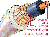
Find your wire and cable here!
Sponsored Sites

