Transmission Lines
INTRODUCTION
TRANSMISSION LINES
are devices designed to guide electrical energy from one point to
another. They are used, for example, to transfer the output rf energy of
a transmitter to an antenna. This energy will not travel through normal
electrical wire without great losses.
Although the antenna can be connected directly to the transmitter, the antenna is usually located some distance away from the transmitter. On board a ship, the transmitter is located inside a radio room and its associated antenna is mounted on a mast. A conducting line is used to connect the transmitter and the antenna.
The line has a single purpose for both the transmitter and the antenna. This purpose is to transfer the energy output of the transmitter to the antenna with the least possible power loss. How well this is done depends on the special physical and electrical characteristics (impedance and resistance) of the line.
TERMINOLOGY
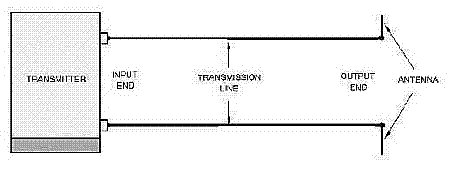
All conducting lines have two ends (see the figure below). The end of a two-wire line connected to a source is ordinarily called the INPUT END or the GENERATOR END. Other names given to this end are TRANSMITTER END, SENDING END, and SOURCE. The other end of the line is called the OUTPUT END or RECEIVING END. Other names given to the output end are LOAD END and SINK.

Basic transmission line.
You can describe a conductor in terms of its impedance. The ratio of voltage to current (Ein/Iin) at the input end is known as the INPUT IMPEDANCE (Zin). This is the impedance presented to the transmitter by the line and its load, the antenna.
The ratio of voltage to current at the output (Eout/Iout) end is known as the OUTPUT IMPEDANCE (Zout). This is the impedance presented to the load by the line and its source. If an infinitely long conductor could be used, the ratio of voltage to current at any point on that line would be some particular value of impedance. This impedance is known as the CHARACTERISTIC IMPEDANCE.
The five types of transmission mediums that we will discuss in this section include:
1. PARALLEL-LINE
2. TWISTED PAIR
3. SHIELDED PAIR
4. COAXIAL LINE
5. WAVEGUIDES
The use of a particular conductor depends, among other things, on the applied frequency, the power-handling capabilities, and the type of installation.
NOTE: In the following paragraphs,
we will mention LOSSES several times. We will discuss these losses more
thoroughly under "LOSSES IN TRANSMISSION LINES."
Types of mediums
Coaxial lines
Waveguides
Line losses
Line length
Line theory
Leakage Current
Characteristic impedance and the infinite line
Voltage change along a transmission line
An infinite line
Velocity of Wave Propagation
Determining characteristic impedance
Line shorts


