DC Motors
INTRODUCTION
DC motors are mechanical workhorses that can be used in many different ways. Many large pieces of equipment depend on a direct current motor for their power to move. The speed and direction of rotation of a direct current motor are easily controlled. This makes it especially useful for operating equipment, such as winches, cranes, and missile launchers, which must move in different directions and at varying speeds.
PRINCIPLES OF OPERATION
The operation of a direct current motor is based on the following principle: A current-carrying conductor placed in a magnetic field, perpendicular to the lines of flux, tends to move in a direction perpendicular to the magnetic lines of flux.
There is a definite relationship between the direction of the magnetic field, the direction of current in the conductor, and the direction in which the conductor tends to move. This relationship is best explained by using the RIGHT-HAND RULE FOR MOTORS as shown in the illustration below.
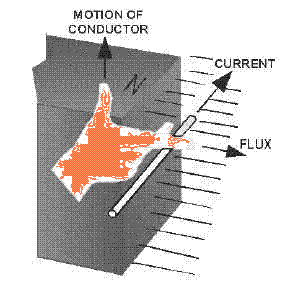
Right hand rule for motors.
To find the direction of motion of a conductor, extend the thumb, forefinger, and middle finger of your right hand so they are at right angles to each other. If the forefinger is pointed in the direction of magnetic flux (north to south) and the middle finger is pointed in the direction of current flow in the conductor, the thumb will point in the direction the conductor will move.
(If you are interested in adding an electric motor to a model car or other hobby visit our friends at Diecast-Utopia.com. With the knowledge you gain here it should be a breeze to build or install a direct current motor into any project).
Stated very simply, a dc motor rotates as a result of two magnetic fields interacting with each other. The armature of a dc motor acts like an electromagnet when current flows through its coils. Since the armature is located within the magnetic field of the field poles, these two magnetic fields interact. Like magnetic poles repel each other, and unlike magnetic poles attract each other. As in the dc generator, the dc motor has field poles that are stationary and an armature that turns on bearings in the space between the field poles. The armature of a dc motor has windings on it just like the armature of a dc generator. These windings are also connected to commutator segments. A dc motor consists of the same components as a dc generator. In fact, most dc generators can be made to act as motors, and vice versa.
Look at the simple dc motor shown in the illustration below. It has two field poles, one a north pole and one a south pole. The magnetic lines of force extend across the opening between the poles from north to south.
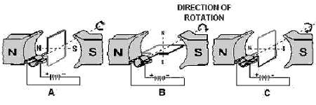
Direct current motor armature rotation.
The armature in this simple dc motor is a single loop of wire, just as in the simple armature you studied at the beginning of the chapter on dc generators. The loop of wire in the dc motor, however, has current flowing through it from an external source. This current causes a magnetic field to be produced. This field is indicated by the dotted line through the loops. The loop (armature) field is both attracted and repelled by the field from the field poles. Since the current through the loop goes around in the direction of the arrows, the north pole of the armature is at the upper left, and the south pole of the armature is at the lower right, as shown in the illustration above, (view A).
Of course, as the loop (armature) turns, these magnetic poles turn with it. Now, as shown in the illustrations, tovehe north armature pole is repelled from the north field pole and attracted to the right by the south field pole. Likewise, the south armature pole is repelled from the south field pole and is attracted to the left by the north field pole.
This action causes the armature to turn in a clockwise direction, as shown in view (B). After the loop has turned far enough so that its north pole is exactly opposite the south field pole, the brushes advance to the next segments. This changes the direction of current flow through the armature loop. Also, it changes the polarity of the armature field, as shown in view (C). The magnetic fields again repel and attract each other, and the armature continues to turn.
In this simple motor, the momentum of the
rotating armature carries the armature past the position where the
unlike poles are exactly lined up. However, if these fields are exactly
lined up when the armature current is turned on, there is no momentum to
start the armature moving. In this case, the motor would not rotate. It
would be necessary to give a motor like this a spin to start it. This
disadvantage does not exist when there are more turns on the armature,
because there is more than one armature field. No two armature fields
could be exactly aligned with the field from the field poles at the same
time.
Counter emf in Direct Current Motors
Different types of DC motors
Armatures in Direct Current Motors
Motor-speed and rotation
Armature reaction and manual and automatic starters


Download the NEETS for your own library.

If you would like to download a module or the entire set, we just require a small fee to ensure your manuals are virus free from our secure server. Just click on the highlighted NEETS link.
Become a loyal member to our site. It's free!
Site Search

Tweet


Translate your page
If English is not your first language you can Translate the text on this page to any one of the languages found in the drop down menu. Select your language from the list for an instant translation.
Looking for something unique for your project? Just enter a keyword into the box to search for your item on Amazon
Related Pages

Docircuits interactive circuit simulator

Become an Electronics Technician

Convert most anything with this utility

