Meters
OHM METERS and MEGGERS are two instruments most commonly used to check the continuity (a complete circuit), or to measure the resistance of a circuit or circuit element. The first device is widely used to measure resistance and check the continuity of electrical circuits and devices. Its range usually extends to only a few megohms.
The megger is widely used for measuring insulation resistance, such as between a wire and the outer surface of the insulation, and insulation resistance of cables and insulators. The range of a megger may extend to more than 1,000 megohms.
The 'ohmmeter' consists of a dc measuring device, with a few added features. The added features are:
1. A dc source of potential (usually a 3-volt battery)
2. One or more resistors (one of which is variable)
3. A simple circuit for this device is shown in the figure below.
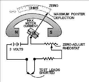
The pointer deflection is controlled by the amount of battery current passing through the moving coil. Before measuring the resistance of an unknown resistor or electrical circuit, the test leads are first shorted together, as shown in the figure below.
With the leads shorted, the device is calibrated for proper operation on the selected range. While the leads are shorted, current is maximum and the pointer deflects a maximum amount, somewhere near the zero position on the ohms scale. Because of this current through the device with the leads shorted, it is necessary to remove the test leads when you are finished using the unit.
If the leads were left connected, they could come in contact with each other and discharge the devices battery. When the variable resistor (rheostat) is adjusted properly, with the leads shorted, the pointer of the unit will come to rest exactly on the zero position. This indicates ZERO RESISTANCE between the test leads, which, in fact, are shorted together.
The zero reading of a series-type is on the right-hand side of the scale, where as the zero reading for an ammeter or a voltmeter is generally to the left-hand side of the scale. (There is another type of device which is discussed a little later on in this section.) When the test leads of an ohmmeter are separated, the pointer will return to the left side of the scale. The interruption of current and the spring tension act on the movable coil assembly, moving the pointer to the left side (¥) of the scale.

A simple measuring device circuit.
USE
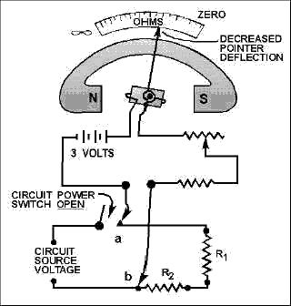
After the device is adjusted for zero reading, it is ready to be connected in a circuit to measure resistance. A typical circuit and device arrangement is shown in the next figure below.

Measuring circuit resistance.
The power switch of the circuit to be measured should always be in the OFF position. This prevents the source voltage of the circuit from being applied across the device, which could cause damage to the units movement.
The test leads of the device are connected in series with the circuit to be measured (the figure below). This causes the current produced by the 3-volt battery of the meter to flow through the circuit being tested. Assume that the units test leads are connected at points a and b of the figure above.
The amount of current that flows through the units coil will depend on the total resistance of resistors R1 and R2, and the resistance of the device. Since the unit has been preadjusted (zeroed), the amount of coil movement now depends solely on the resistance of R1and R2. The inclusion of R1 and R2 raises the total series resistance, decreasing the current, and thus decreasing the pointer deflection.
The pointer will now come to
rest at a scale figure indicating the combined resistance of R1 and R2.
If R1 or R2, or both, were replaced with a resistor(s) having a larger
value, the current flow in the moving coil of the device would be
decreased further. The deflection would also be further decreased, and
the scale indication would read a still higher circuit resistance.
Movement of the moving coil is proportional to the amount of current
flow.
Ranges and multiplication jacks
Shunt type and safety precautions
Megger and safety precautions
Multimeters
Parallax errors
Other Types
Vibrating and Disk Frequency


