Dual Trace Components
Dual trace components are used to determine the amplitude of a signal. You will use these dual trace components to determine the amplitude of a signal. Notice in the figure below that the highlighted section at the upper left of the scope looks just the same as the section at the lower left of the scope.
This reveals the dual-trace capability section of the scope. The upper left section is the CH (channel) 1 input and is the same as the CH 2 input at the lower left. An input to both inputs at the same time will produce two independent traces on the CRT and use the dual-trace capability of the scope.

Components that determine amplitude.
For purposes of this introductory discussion, we will present only CH (channel) 1. You should realize that the information presented also applies to CH 2.
Vertical POSITION Control
The vertical POSITION control allows you to move the beam position up or down, as discussed earlier.
Input Connector
The vertical input (or signal input) jack connects the signal to be examined to the vertical-deflection amplifier. Some oscilloscopes may have two input jacks, one labeled AC and the other labeled DC. Other models may have a single input jack with an associated switch, such as the AC GRD DC switch in the figure above.
This switch is used to select the ac or dc connection. In the DC position, the signal is connected directly to the vertical-deflection amplifier; in the AC position, the signal is first fed through a capacitor. The figure below shows the schematic of one arrangement.

Vertical input arrangement.
The VERTICAL-DEFLECTION AMPLIFIER increases the amplitude of the input signal level required for the deflection of the CRT beam. The deflection amplifier must not have any other effect on the signal, such as changing the shape (called DISTORTION). The next figure below shows the results of distortion occurring in a deflection amplifier.

Deflection amplifier distortion.
Attenuator Control
An amplifier can handle only a limited range of input amplitudes before it begins to distort the signal. Signal distortion is prevented in oscilloscopes by the incorporation of circuitry that permits adjustment of the input signal amplitude to a level that prevents distortion from occurring. This adjustment is called the ATTENUATOR control in some scopes (VOLTS/DIV and VAR in figure 1 above). This control extends the usefulness of the oscilloscope by enabling it to handle a wide range of signal amplitudes.
The attenuator usually consists of two controls. One is a multiposition (VOLTS/DIV) control, and the other is a variable (VAR) potentiometer. Each position of the control may be marked either as to the amount of voltage required to deflect the beam a unit distance, such as VOLTS/DIV, or as to the amount of attenuation (called the DEFLECTION FACTOR) given to the signal, such as 100, 10, or 1.
Suppose the .5 VOLTS/DIV position were selected. In this position, the beam would deflect vertically 1 division for every 0.5 volts of applied signal. If a sine wave occupied 4 divisions peak-to- peak, its amplitude would be 2 volts peak-to-peak (4 ´ 0.5), as shown in the figure below.

Sine wave attenuation.
The vertical attenuator control (VOLTS/DIV in the 2nd figure) provides a means of adjusting the input signal level to the amplifiers by steps. These steps are sequenced from low to high deflection factors. The potentiometer control (VAR in the figure below) provides a means of fine, or variable, control between steps. This control may be mounted separately, or it may be mounted on the attenuator control. When the control is mounted separately, it is often marked as FINE GAIN or simply GAIN. When mounted on the attenuator control, it is usually marked VARIABLE or VAR.
The
variable control adds attenuation to the step that is selected. Since
accurately calibrating a potentiometer is difficult, the variable
control is either left unmarked or the front panel is marked off in some
convenient units, such as 1-10 and 1-100. The attenuator control,
however, can be accurately calibrated. To do this, you turn off the
variable control to remove it from the attenuator circuit. This position
is usually marked CAL (calibrate) on the panel, or an associated light
indicates if the VAR control is on or off. In the next figure, the light
called UNCAL indicates the VAR control is in the uncalibrated position.


Download the NEETS for your own library.
If you would like to download a module or the entire set, we just require a small fee to ensure your manuals are virus free from our secure server. Just click on the highlighted NEETS link.
Become a loyal member to our site. It's free!
Site Search

Tweet


Translate your page
If English is not your first language you can Translate the text on this page to any one of the languages found in the drop down menu. Select your language from the list for an instant translation.
Looking for something unique for your project? Just enter a keyword into the box to search for your item on Amazon
Related Pages
Docircuits interactive circuit simulator

Become an Electronics Technician

Convert most anything with this utility
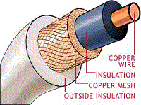
Find your wire and cable here!
Sponsored Sites

