Diode Identification
There are many types of diode identification varying from the size of a pinhead (used in subminiature circuitry) to large 250-ampere diodes (used in high-power circuits).
Because
there are so many different types of diodes, some system of
identification is needed to distinguish one diode from another. This is
accomplished with the (semiconductor)
diode identification
system shown in the illustration below.

Standard diode-identification system.
This system is not only used for diodes but transistors and many other special semiconductor devices as well. As illustrated in the picture, the system uses numbers and letters to identify different types of semiconductor devices.
The first number in the system indicates the number of junctions in the semiconductor device and is a number, one less than the number of active elements. Thus 1 designates a diode; 2 designates a transistor (which may be considered as made up of two diodes); and 3 designates a tetrode (a four-element transistor).
The letter "N" following the first number indicates a semiconductor. The 2- or 3-digit number following the letter"N" is a serialized identification number. If needed, this number may contain a suffix letter after the lastdigit. For example, the suffix letter "M" may be used to describe matching pairs of separate semiconductor devices or the letter "R" may be used to indicate reverse polarity.
Other
letters are used to indicate modified versions of the device which can
be substituted for the basic numbered unit. Forexample, a semiconductor
diode designated as type 1N345A signifies a two-element diode (1) of
semiconductor material (N) that is an improved version (A) of type 345.
When working with these different types of diodes, it is also necessary
to distinguish one end of the diode from the other (anode from cathode).
For this reason, manufacturers generally code the cathode endof the diode with a "k," "+," "cath," a color dot or band, or by an unusual shape (raised edge or taper) as shown in the next illustration below. In some cases, standard color code bands are placed on the cathode end of the diode. This serves two purposes: (1) it identifies the cathode end of the diode, and (2) it also serves to identify the diode by number.

Semiconductor diode marking system.
The standard diode identification color code system is shown in the last illustration. Take, for example, a diode with brown, orange, and white bands at one terminal and figure out its identification number. With brown being a "1," orange a "3," and white "9," the device would be identified as a type 139 semiconductor diode, or specifically 1N139.

Semiconductor diode color system.
Keep in mind, whether the diode is a small crystal type or a large power rectifier type, both are still represented schematically.
(back) (top) (next) (return to diodes page)


Download the NEETS for your own library.

If you would like to download the entire set or just one module for a small fee, click on the highlighted NEETS link.
Become a loyal member to our site. It's free!
Site Search

Tweet


Translate your page
If English is not your first language you can Translate the text on this page to any one of the languages found in the drop down menu. Select your language from the list for an instant translation.
Looking for something unique for your project? Choose from the drop down menu for quick access to the item you seek.
Related Pages
Docircuits interactive circuit simulator

Become an Electronics Technician

Convert most anything with this utility
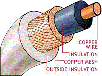
Find your wire and cable here!
Sponsored Sites

