Waveguides
THEORY OF WAVEGUIDES
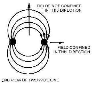
The two-wire transmission line used in conventional circuits is inefficient for transferring electromagnetic energy at microwave frequencies. At these frequencies, energy escapes by radiation because the fields are not confined in all directions, as shown in the first illustration.

Fields confined in two directions only.
RF plumbing differ in their geometry which can confine energy in one dimension such as in slab types or two dimensions as in fiber or channel types. In addition, different types are needed to guide different frequencies: an optical fiber guiding light (high frequency) will not guide microwaves (which have a much lower frequency). As a rule of thumb, the width of a waveguide needs to be of the same order of magnitude as the wavelength of the guided wave.
Waves in open space propagate in all directions, as spherical waves. In this way they lose their power proportionally to the square of the distance; that is, at a distance R from the source, the power is the source power divided by R2. The waveguide confines the wave to propagation in one dimension, so that (under ideal conditions) the wave loses no power while propagating.
Waves are confined inside the waveguide due to total reflection from the waveguide wall, so that the propagation inside the waveguide can be described approximately as a "zigzag" between the walls. This description is exact for electromagnetic waves in a hollow metal tube with a rectangular or circular cross section.
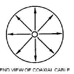
Coaxial lines are more efficient than two-wire lines for transferring electromagnetic energy because the fields are completely confined by the conductors as shown in the next illustration.

Fields confined in all directions.
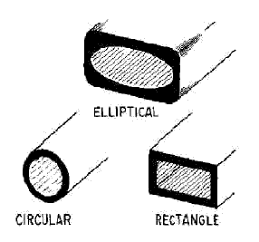
RF plumbing is the most efficient way to transfer electro-magnetic energy. WAVEGUIDES are essentially coaxial lines without center conductors. They are constructed from conductive material and may be rectangular, circular, or elliptical in shape, as shown in the last illustration below.

Waveguide shapes.
Advantages and Disadvantages
Developing the waveguide from parallel lines
Energy-propagation and The "E" field
H-field: Energy propagation continued-
Boundry-conditions and wavefronts
Boundry-conditions-continued: reflections
Modes-of-operation: a continuation of the study of RF plumbing
Mode numbering systems: Transverse electric and transverse magnetic
Input/output methods
Injecting energy into RF plumbing
Impedance matching
Terminations
RF Plumbing and bends
Joints and maintenance
RF plumbing evices
Cavity resonators and cavity tuning
Junctions: the E, H and Magic T type junction and the Hybrid ring
Ferrite-devices: attenuators, isolators, and phase shifters


