RADAR-Parts
Introduction to RADAR-Parts and Their Subsystems
Any radar system has several major subsystems that perform standard functions. A typical radar system consists of a SYNCHRONIZER (also called the TIMER or TRIGGER GENERATOR), a TRANSMITTER, a DUPLEXER, a RECEIVER, and an INDICATOR. These major subsystems were briefly described in the previous tutorial on basic RADAR concepts.
This chapter will describe the operation of RADAR-parts such as the
synchronizer, transmitter, duplexer, and receiver of a typical pulse
radar system and briefly analyze the circuits used. The next section will
describe typical indicator and antenna RADAR-parts. Because radar-parts systems
vary widely in specific design, only a general description of
representative circuits is presented in this chapter.
SYNCHRONIZERS
The synchronizer is often referred to as the "heart" of the radar system because it controls and provides timing for the operation of the entire system. Other names for the synchronizer are the TIMER and the KEYER. We will use the term synchronizer in our discussion. In some complex systems the synchronizer is part of a system computer that performs many functions other than system timing.
SYNCHRONIZER FUNCTION The specific function of the synchronizer is to produce TRIGGER PULSES that start the transmitter, indicator sweep circuits, and ranging circuits.
Timing
or control is the function of the majority of circuits in radar.
Circuits in a radar set accomplish control and timing functions by
producing a variety of voltage waveforms, such as square waves, sawtooth
waves, trapezoidal waves, rectangular waves, brief rectangular pulses,
and sharp peaks. Although all of these circuits can be broadly
classified as timing circuits, the specific function of any individual
circuit could also be wave shaping or wave generation.
SYNCHRONIZER OPERATION
Radar-parts systems may be classified as either SELF-SYNCHRONIZED or EXTERNALLY SYNCHRONIZED systems. In a self-synchronized system, the timing trigger pulses are generated in the transmitter. In an externally synchronized system, the timing trigger pulses are generated by a MASTER OSCILLATOR, which is usually external to the transmitter.
The master oscillator in an externally synchronized system may be a BLOCKING OSCILLATOR, a SINE-WAVE OSCILLATOR, or an ASTABLE (FREE-RUNNING) MULTI-VIBRATOR. When a blocking oscillator is used as a master oscillator, the timing trigger pulses are usually obtained directly from the oscillator. When a sine-wave oscillator or an astable multivibrator is used as a master oscillator, pulse-shaping circuits are required to form the necessary timing trigger pulses. In an externally synchronized radar system, the pulse repetition rate (prr) of the timing trigger pulses from the master oscillator determines the prr of the transmitter.
In a self-synchronized radar system, the prr of the timing trigger pulses is determined by the prr of the modulator or transmitter.
Associated with every radar-parts system is an indicator, such as a cathode-ray tube, and associated circuitry. The indicator can present range, bearing, and elevation data in visual form so that a detected object may be located. Trigger pulses from the synchronizer are frequently used to produce gate (or enabling) pulses. When applied to the indicator, gate pulses perform the following functions:
1. Initiate and time the duration of the indicator sweep voltage
2. Intensify the cathode-ray tube electron beam during the sweep period so that the echo pulses may be displayed
3. Gate a range marker generator so that range marker signals may be superimposed on the indicator presentation.
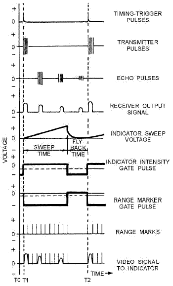
The figure below shows the time relationships of the various waveforms in a typical radar set. The timing trigger pulses are applied to both the transmitter and the indicator. When a trigger pulse is applied to the transmitter, a short burst of transmitter pulses (rf energy) is generated.

Time relationship of waveforms.
This energy is conducted along a transmission line to the radar antenna. It is radiated by the antenna into space. When this transmitter energy strikes one or more reflecting objects in its path, some of the transmitted energy is reflected back to the antenna as echo pulses. Echo pulses from three reflecting targets at different ranges are illustrated in the figure above.
These echoes are converted to the corresponding receiver output signals as shown in the figure. The larger initial and final pulses in the receiver output signal are caused by the energy that leaks through the duplexer when a pulse is being transmitted.
The indicator sweep voltage shown in the figure above is initiated at the same time the transmitter is triggered. In other applications, it may be more desirable to delay the timing trigger pulse that is to be fed to the indicator sweep circuit. Delaying the trigger pulse will initiate the indicator sweep after a pulse is transmitted.
Note in the figure above that the positive portion of the indicator intensity gate pulse (applied to the cathode-ray tube control grid) occurs only during the indicator sweep time. As a result, the visible cathode-ray tube trace occurs only during sweep time and is eliminated during the flyback (retrace) time. The negative portion of the range-marker gate pulse also occurs during the indicator sweep time. This negative gate pulse is applied to a range-marker generator, which produces a series of range marks.
The
range marks are equally spaced and are produced only for the duration
of the range-marker gate pulse. When the range marks are combined
(mixed) with the receiver output signal, the resulting video signal
applied to the indicator may appear as shown at the bottom of the figure
above.
Basic Synchronizer Circuits
Transmitters and the RADAR Modulator
Modulator-Storage-Element and the artificial transmission line
Pulse-forming-networks and Modulator switching devices
The Keyed-Oscillator Transmitter
The Power-Amplifier Transmitter
The Frequency Synthesizer
Basic Duplexer Operation and the Tr-Tube
Atr-tube and Parallel Connected Duplexer Operation
Series-Connected-Duplexer Operation and Duplexer Types
Hybrid-Ring-Duplexer and the RADAR Receiver
RADAR-Receiver-Requirements and the receiver block diagram
The Single-ended or Unbalanced crystal mixer
IF-Amplifier-Stage: Detectors and Video Amplifiers
Receiver-Special-Circuits: automatic gain control, sensitivity time control, and antijamming circuits
Special-Receivers and the Moving Target Indicator (mti) System
Logarithmic-Receivers and the monopulse receiver


